- HOME
-
- Products overview
- 14. Trimming potentiometers
- 13. Potentiometers
- 12. Custom designed types
- 11. Interference suppression filters
- 10. Radio interference suppression chockes
- 9. Suppression bushing capacitors
- 8. Delta RFI capacitors
- 7. Radiointerference suppression capacitors and RC - components
- 6. Motor capacitors
- 5. High voltage capacitors
- 4. Capacitors for High frequency induction heating
- 3. Pulse capacitors
- 2. Metallized polypropylene film capacitors
- 1. Metallized polyester film capacitors
-
- certificates - general informations
- 13 - IECEE-CB certificate of the motor capacitors MKP 391, MKP 393, MKP 395 No.: CZ - 1596
- 12 - IECEE-CB certificate of the suppression capacitors class X2 C 304 - C 306 No.: CZ - 1408
- 11 - IECEE-CB certificate of the type KPI 346 - 349 capacitors No.: CZ - 1181
- 10 - IECEE-CB certificate of the MKP 380 - 384 No.: CZ - 1163, axial construction
- 9 - IECEE-CB certificate of the MKP 360 - 364 No.: CZ - 1162, prismatic boxed construction
- 8 - IECEE-CB certificate of the MKT 225 - 229 No.: CZ - 1056, prismatic boxed construction
- 7 - IECEE-CB certificate of the type KPI pulse capacitors No.: CZ - 1055
- 6 - IECEE-CB certificate of the MKT 205 - 209 No.: CZ - 1042, axial construction
- 5 - IECEE-CB certificate of the suppression R-C components No.: CZ - 972
- 4 - IECEE-CB certificate of the motor capacitors MKP 351, 353 No.: CZ - 926, prismatic boxed construction
- 3 - IECEE-CB certificate of the motor capacitors MKP 352, 354 No.: CZ - 786, axial flat construction
- 2 - IECEE-CB certificate of the suppression capacitors class Y2 No.: CZ - 738
- 1 - IECEE-CB certificate of the suppression capacitors class X2 No.: CZ - 723
-
- 9 - Final provisions
- 8 - Dispute resolution
- 7 - Liability for defects, complaint procedure
- 6 - Payment terms
- 5 - Delivery terms and delays
- 4 - Creation of a purchase contract (order, order confirmation)
- 3 - Prices, demand, quotation
- 2 - Information about delivered goods
- 1 - General provisions
- News
- Quality policy
- Environmental impact
-
- 2 - Adobe Acrobat Reader 7 - EN - full version [ 21,2 MB ]
- 1 - Adobe Acrobat Reader 7 - EN - basic version [ 13,1 MB ]
- Write us
CONTACT :
Electronicke soucastky CZ, Inc.
Syllabova 2980/37A
703 00 Ostrava, Czech Republic
VAT: CZ25852361
Phone: +420 595 781 623
E-mail: Write us
Electronicke soucastky CZ, Inc.
Syllabova 2980/37A
703 00 Ostrava, Czech Republic
VAT: CZ25852361
Phone: +420 595 781 623
E-mail: Write us


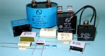
P roducts
Film capacitors - general information
There are two basic groups of capacitors:
Film-foil capacitors, which ensure very high pulse load and current handling capability, very good capacitance stability and reliability, high insulation resistance and very low dielectric losses. Special construction of this capacitors allow also the self healing property.
Metallized film capacitors with excellent self healing property, very small dimensions. The contacting is made by spraying of metal alloys onto windings face ends. The leads are then welded on these sprayed faces. By the spraying are the windings short circuited. This technology ensures very low self inductance and high resonance frequency of the capacitors.
The dielectric materials used in capacitors are:
Polyester film, or metallized polyester film
- MKT capacitors
Polypropylene film or metallized polypropylene film.
- MKP, MKPI and KPI pulse capacitors
A comparison of the characteristics of the capacitors is shown in the following table:
Dielectric properties of capacitors
| Type | MKT | MKP |
| Relative dielectric constant e | 3,2 | 2,2 |
| DF at 1 kHz, tan d | 0,005 | 0,0005 |
| Ris [G W x mF] | 25 | 100 |
| Dielectric absorption [%] | 0,2 | 0,05 |
| Capacitance Drift D C/C [%] | 1,5 | 0,5 |
| Moisture absorption [%] | 0,4 | 0,01 |
| Maximum temperature [°C] | 100 - 125 | 85 - 100 |
| Tc [ppm/°C], [10-6/°C] | +400, ± 200 | -200, ± 100 |
MKT capacitors have high dielectric constant, high dielectric strength, excellent self-healing properties, good stability, positive temperature coefficient (+400ppm/°C). MKT capacitors are regarded as general purpose capacitors and are preferably used for DC applications as decoupling, blocking, bypassing and noise suppressing capacitors.
MKP, MKPI and KPI capacitors have superior electrical parameters, very low dielectric losses, very high insulation resistance, very low dielectric absorption and very high dielectric strength, excellent moisture resistance and very good long term stability. Temperature coefficient is negative (-200ppm/°C).
Typical applications:
- AC and high pulse applications at high frequencies
- switch mode power supplies and snubber applications
- filter circuits
- sample and hold applications and other applications where are the excellent features necessary.
Rated capacitance
Rated capacitance of a capacitor is measured at 1 or 10kHz and at +20°C, 1kHz is reference frequency. Detailed description of measuring methods and measuring conditions you find in generic standard IEC 60384-1 and in corresponding sectional specifications.
Dissipation factor
express the losses of the dielectric material, contact-resistance and insulation resistance. Dissipation factor is the ratio between the resistive and the reactive part of the impedance of the capacitor, expressed by tgd.
Dissipation factor change as a function of temperature at 1 kHzz
Dissipation factor change as a function of frequency (room temperature)
The dissipation factor is especially important when the capacitor operates on AC. The losses in capacitor causes heating of the capacitor. The heating may lead to a destructive breakdown at high frequencies if the losses are high.
Equivalent series resistance, ESR
is the resistive part of equivalent series circuit. It depends on the resistivity of electrodes, internal connections contacts and dielectric losses. It is frequency and temperature dependent.
Ls - Parasitic series inductance
Rs - Series resistance of leads and internal contacts
Rp - Parallel insulation resistance
C - Capacitance of capacitors
Insulation resistance
is measured at reference-voltage, usually 100V, possible 10VDC or up to 1000VDC, after 1min. charging and at +20°C and relative humidity RH=50%. Basically 100VDC measuring voltage is used. For capacitor values C>0,33mF the RIS
is expressed as time constant t = R x C [MW; mF] The RIS decreases with increasing temperature.
Rated voltage
The rated voltage is the max. direct voltage or the max. RMS alternating voltage, or the peak value of a pulse voltage, which may be applied continuously to the capacitor at any temperature between the lower category temperature and up to a rated temperature of +85°C.
For temperatures higher than the rated temperature +85°C the rated voltage has to be derated in dependence upon the type of used dielectric, to prevent or exclude any damages of the capacitors.
Superimposed AC voltage
when alternating voltage are present, eventually in addition to direct voltage, the sum of both, UDC and the peak value of UAC must not exceed the rated voltage UR of the capacitor.
AC applications
Wwhen the capacitor is used in any AC applications internal heating may arise, which is caused by the heating effect of the
current flowing through the internal resistance of the capacitor. The dissipated power by the capacitor is
PD = (URMS)2 x 2pfC x tgd
The max. permissible PD must not cause the increasing of the surface temperature of the capacitor under working conditions higher as DTS < 10°C
For the operations in the higher frequency range, the permissible AC voltage has to be derated. The permissible AC voltages are shown in the graphs Permissible AC voltage versus Frequency for each Type of capacitor.
When using the capacitors in a high frequency circuit, pleas apply the max. voltage which does not exceed the value shown in the corresponding diagram.
Climatic category
appoint the climatic conditions in which the capacitor may be operated continuously. According to IEC 60068-1 the climatic category is expressed by three groups of numbers 55/100/56.
First group define the lower category temperature TMIN (-55°C), which is also the test temperature for test Aa cold, IEC 60068-2-1.
Second group define the upper category temperature TMAX (+100°C), which is the test temperature for test Ba-dry heat in accordance with IEC 60068-2-2.
The third group specify the number of days of exposure by the Damp heat steady state-Ca Test at 95% relative humidity and +40°C in accordance with IEC 60068-2-3
Maximum Temperature
or upper category temperature is the highest temperature at which a capacitor may still be working. At pulse or AC
operation, the sum of the max. ambient temperature and the temperature increase by the load conditions ( 10°C), must not exceed the upper category temperature.
Pulse load and current handling capability Permissible pulse rise time is defined by dU/dt [V/msec]
Voltage pulses with rapid voltage changes dU/dt will lead to strong current IP (peak current) in the capacitor
Pulse current IP = C x dU/dt
flowing through the capacitor, causes a local heating of the contact area of the capacitor, between the sprayed-on metal
terminations and the metal or metallized layers. To prevent the risk of damage, minimal resistance in series with the capacitor, which is connected to the source with very low RIN is necessary
RS = UR/(C x dU/dt)
The dU/dt is referred to the rated voltage UR.
If the applied pulse UOP voltage is lower than UR voltage, higher dU/dt value can be permitted
dUOP/dt = dUR/dt x UR/UOP
Capacitance changes up and down with temperature due to the dielectric constant and the temperature coefficient of the dielectric material.
The temperature coefficient is expressed by ac = C2 - C1/C1(T2-T1)
C1: capacitance at the temperature T1
C2: capacitance at the temperature T2
reference temperature is T1
ac is expressed in ppm/°C.
Depending upon the dielectric material the aC can either be positive +400 ppm - MKT capacitors, or negative
200 ppm -
MKP capacitors.
Capacitance change versus temperature
Equivalent series inductance: ESL
The real capacitor has a certain self inductance due to the length of connections and the construction of capacitive element. This inductances represents the Equivalent Series Inductance.
The value of this inductance is indicated by resonant frequency of the capacitor at +20°C ±5°C. At resonant frequency the capacitive reactance equals the inductive reactance
1/(2pf x C) = 2pf x ESL
The ESL affects the impedance Z(f) of the capacitor.
![]()
The construction of the capacitors enables to achieve very low ESL and high resonance frequency of the capacitors. At resonance frequency the impedance of the capacitor is minimal and is equal to ESR of the capacitors. Self inductance of the capacitors depends on the length of leads and on the length of the body of capacitor. The capacitors in prismatic cases end leads with the length 2mm have the typical ESL.
The round or oval capacitors with axial leads have ESL approximately 1nH per 1mm leads and body length.
Rated RMS Current IRMS is the highest permissible RMS value of the continuous current flowing through the capacitor at the max. case temperature of +70°C.
Operating at the rated RMS current, the capacitor produces a case temperature rise of about +10°C over the ambient due to the resistive losses. The RMS current IRMS must be derated taking into account the ambient temperature.
The max power which may be dissipated by the capacitor is PDlim = D TMAX / J R
JR - thermal resistance of the capacitor [°C/W]
DTMAX - permissible temperature increasing of the capacitor-surface
Informative thermal resistance of the capacitor-cases are in following table.
Simply you can calculate the max permissible dissipated power of the capacitor by using following formula:
PD = K x S x DTMAX
S - surface of the capacitors-body [cm2]
DTMAX : 10°C
K - coefficient 1,0 - 2,5
lower K values are to be used for the general purpose metallized film capacitors higher K= 2 - 2,5 values for the
pulse capacitors, IGBT, GTO and special construction.
Technical parameters of the capacitors - cases
| Rozměry pouzdra [mm] | Rozteč | Povrch [cm2] | Tepelný odpor | P Dlim | ||
| B | H | L | P | S | J R [°C/W] | [W] |
| 6 | 15 | 26,5 | 22,5 | 12,93 | 43 | 0,32 |
| 7 | 16 | 26,5 | 22,5 | 14,43 | 41 | 0,36 |
| 8,5 | 17 | 26,5 | 22,5 | 16,405 | 38 | 0,41 |
| 10 | 18,5 | 26,5 | 22,5 | 18,805 | 36 | 0,47 |
| 11 | 20 | 26,5 | 22,5 | 20,83 | 34 | 0,52 |
| 9 | 17 | 32 | 27,5 | 19,7 | 35 | 0,49 |
| 10 | 20 | 32 | 27,5 | 23,2 | 32 | 0,58 |
| 11 | 20 | 32 | 27,5 | 24,24 | 31 | 0,61 |
| 13 | 22 | 32 | 27,5 | 28,12 | 29 | 0,70 |
| 14 | 28 | 32 | 27,5 | 34,72 | 26 | 0,87 |
| 15 | 24,5 | 32 | 27,5 | 32,63 | 27 | 0,82 |
| 18 | 33 | 32 | 27,5 | 44,52 | 23 | 1,11 |
| 22 | 37 | 32 | 27,5 | 54,04 | 21 | 1,35 |
| 10 | 20 | 42,5 | 37,5 | 29,50 | 28 | 0,74 |
| 11 | 22 | 42,5 | 37,5 | 32,89 | 27 | 0,82 |
| 13 | 24 | 42,5 | 37,5 | 37,69 | 25 | 0,94 |
| 16 | 28,5 | 42,5 | 37,5 | 46,945 | 23 | 1,17 |
| 19 | 32 | 42,5 | 37,5 | 55,51 | 21 | 1,39 |
| 20 | 40 | 42,5 | 37,5 | 67 | 19 | 1,68 |
| 24 | 44 | 42,5 | 37,5 | 78,92 | 17 | 1,97 |
During the operation the capacitor-temperature has always to be lower as the max. operating temperature. Therefore the PD always has to be lower as the PDlim, which the case of the capacitor can radiate. The dissipated power of the capacitor, working with AC, is determined by the working URMS or IRMS, working frequency and tgd(f) of the capacitor.
PD = U2 RMS x tgd x 2pfC = I2 RMS x tgd / 2pfC
The max. value of the URMS under which the capacitor can continuously works is also limited by the ionization-effect, or corona-effect. The ionization effect appears, if the working voltage is to high and can cause a destructive process in the capacitor.
The limited URMS is defined in the range till the working frequency f1. Between f1 and f2 the URMS have to be reduced, not exceed the max permissible dissipation Power in the capacitor according to previous formulas. Between f2 and f3 the IRMS has to be limited by the construction of leads of the capacitor.
For example, if the leads are tinned copper wire
| 0,8mm = 0,5mm2 | IMAX = 7,0A |
| 1,0mm = 0,785mm2 | 9,0A |
| Lugs | 16 - 20A |
| Fastons | 16 - 24A |
| Screws M4 | 20A |
| M6 | 40A |
| M8 | 63A |
| M10 | 100A |
| M12 | 160A |
These statements is to be taken as informative, the practical test in particular applications should always be made in order to verify the correctness of the theoretical assumptions.
Alternating voltage and current versus frequency
Capacitance change as a function of frequency (room temperature)
Quality assurance
The Quality of the electronic components, which the firm ELECTRONIC COMPONENTS CZ, a.s. manufactures and
supplies, is based on the continuous care of the procedures in the manufacturing process. In order to assure the highest
quality and reliability of all components, the parameters has been continuously monitored during all production process
and also in the firm testing-laboratory. The manufacturing process has been certified by ISO 9000 Standards and the
capacitors have been certified in accordance to IECEE-CB system. The IECEE-CB system incorporate about forty international testing laboratories, which are obliged to acknowledge these and guarantee national CB-certificates.
Reliability of electronic components depends on:
- the construction of the components
- manufacturing process
- the application-conditions, electrical stress and temperature
Regarding the first and second condition, the manufacturer guarantees the best care and supplies 100% tested components exclusively. To help the customer to rich optimal conditions and life expectancy of the electronic components we recommend taking into account following legality, which we describe below.
The expected life of the component is the time required to rich the failure. There are the critical failures, as short or open circuit and failures caused by exceeding limiting values of the
critical parameters, for example:
DC/C 10% for MKT capacitors
DC/C 5% for MKP, KPI capacitors
increasing of tgd > 2 x initial limit for MKT
increasing of tgd > 3 x initial limit for MKP, KPI
Failure rate l is the fraction failure divided by the operating time
and it is expressed in FIT, (failure in time
1FIT = 1 x 10⁻⁹/h failure
per 109 hour - components.
The failure rate is referred to the failure rate criteria
l = n/(n x tt)
n : Number of failures
N : Number of tested components
tt : test time in hours
The 1 / l = mean time between failures (MTBF)
The operation time comprises operational time and interruption time as well as the time for storage and transportation. It is referred to +40°C and working voltage UW = 0,5 x UR and upper confidence level of 60%.
Failure rates vs. temperature and voltage
- polyester capacitors
- polyester capacitors
Failure rates vs. temperature and voltage
- polypropylene capacitors
- polypropylene capacitors
The life expectancy of electronic components subjected to a different voltage from the reference-voltage, can be approximately calculated by following formula
LW = LR x (UREF / UW)8
The life expectancy if the working temperature is different, can be calculated by formula
LOP = LTO x 2 (To-Tw)/Ac
To : reference temperature
Tw : working temperature
Ac : Arrhenius coefficient, typical AC = 7
The above formula is derived from Arrhenius equation, describing the ageing of dielectric films in function of the temperature and gives good results if the temperature range taken in consideration, is not to wide. The FIT ratings for other working voltage and other temperature conditions can beset up as follow
l = l REF x CU x CT
CU : Voltage conversion factor
CT : Temperature conversion factor
For good estimation of influence of temperature and working voltage on the service life of the capacitors, which work by AC, you can use following diagrams.
Voltage conversion factor
| Load ratio UW/UR [%] |
Type, Typ MKT |
Type, Typ MKPI, KPI |
| 100 | 6 | 11 |
| 75 | 2,5 | 3 |
| 50 | 1 | 1 |
| 25 | 0,4 | 0,4 |
| 10 | 0,2 | 0,2 |
Temperature conversion factor
| Temperature [°C] | CT |
| 40 | 1 |
| 55 | 2 |
| 70 | 5 |
| 85 | 12 |
| 100 | 33 |
| 125 | 350 |
Further factors, which affect the failure ratings in practical application are
- working environment CE
- influence of the capacity value CC
CC = 1,4 x C0,12
Working environment
| Enviroment | CE |
| Laboratory | 1 |
| Consumer electronic | 1,2 - 1,5 |
| Industrial electronic | 2,0 - 3,0 |
| Automotive electronics | 3,0 - 4,0 |
Influence of the capacity value CC
The failure rate is, of course, a function of time also. Typical components failure rate curve is shown below.
Typical components failure rate curve
The Bath tube curve represents the characteristic shape of the failure rate ower the operation time.
It has three periods.
1. Period, in which early failures occur
2. Period, in which the failure rate is practically constant
3. Period, in which the failures due to wear of the components increase
The failure rates data are referred to the second part of the curve.
To minimalize the influence of early failure rates, the burn-in procedure, or artifical ageing procedure of the components is
used. On request the components are subjected to a defined electrical and thermal stress and thereafter 100% tested and sort.
Quick navigation :
metallized polyester film capacitors |
metallized polypropylene film capacitors |
pulse capacitors |
kondenzátory pro vf indukční ohřev |
high voltage capacitors |
motor capacitors |
radiointerference suppression capacitors and RC - components |
delta RFI capacitors |
suppression bushing capacitors |
radio interference suppression chockes |
interference suppression filters |
custom designed types |
potentiometers |
trimming potentiometers

2026 © Elektronické součástky CZ, a.s., Ostrava